Challenge Overview
Checkpoint phase
We added a checkpoint phase in this challenge, all submissions that submitted before Jan 9, 2019 8:00 AM EST will be considered as checkpoint submissions. We will provide preliminary feedback to all checkpoint submissions, you can submit again after the checkpoint phase. We will choose 5 checkpoint winners, each winner will receive $100 (not included in the main prize $2000/$1000). So the final winner will receive $2100 potentially.
Important deadline
- Checkpoint submission phase deadline: Jan 9, 2019 8:00 AM EST
- Final submission phase deadline: Jan 14, 2019 8:00 AM EST
Challenge Objectives
-
Target environment: Browser (Chrome, Safari, Firefox), Web Application
-
Basic Requirements: Implement an auto layout algorithm to make sure the fiber cables can be connected among Chassis properly.
Project Background
NextGen Inventory Mgmt App is a web application to help our users to quickly explore, spot and review different technical issues that might happen on any device from a large IT Servers Solution.
The app is built based on three.js to render 3D models to the browser.
Technology Stack
Javascript ES6
Three.js
NodeJS
WebGL
Individual requirements
1. Overview of the app
We have built a prototype of the app, but now we have suffered a difficult problem and need your help.
The source code fo the prototype of the app is provided in the forum.
The prototype of the app can simulate the physical layer devices of a network system. The hierarchy of the devices is as below.
-
There are several chassis in the physical layer.
-
Each chassis contains several cards inserted.
-
Each card has several ports.
-
Some ports are connected via Fiber cables.
-
Each endpoint of the fiber cable is associated with an LC connector and an SFP port.
For example, there are two chassis. Let’s name the left chassis has two cards, the right chassis has one card. There are two fiber cables connect two ports of the left chassis and the right chassis.
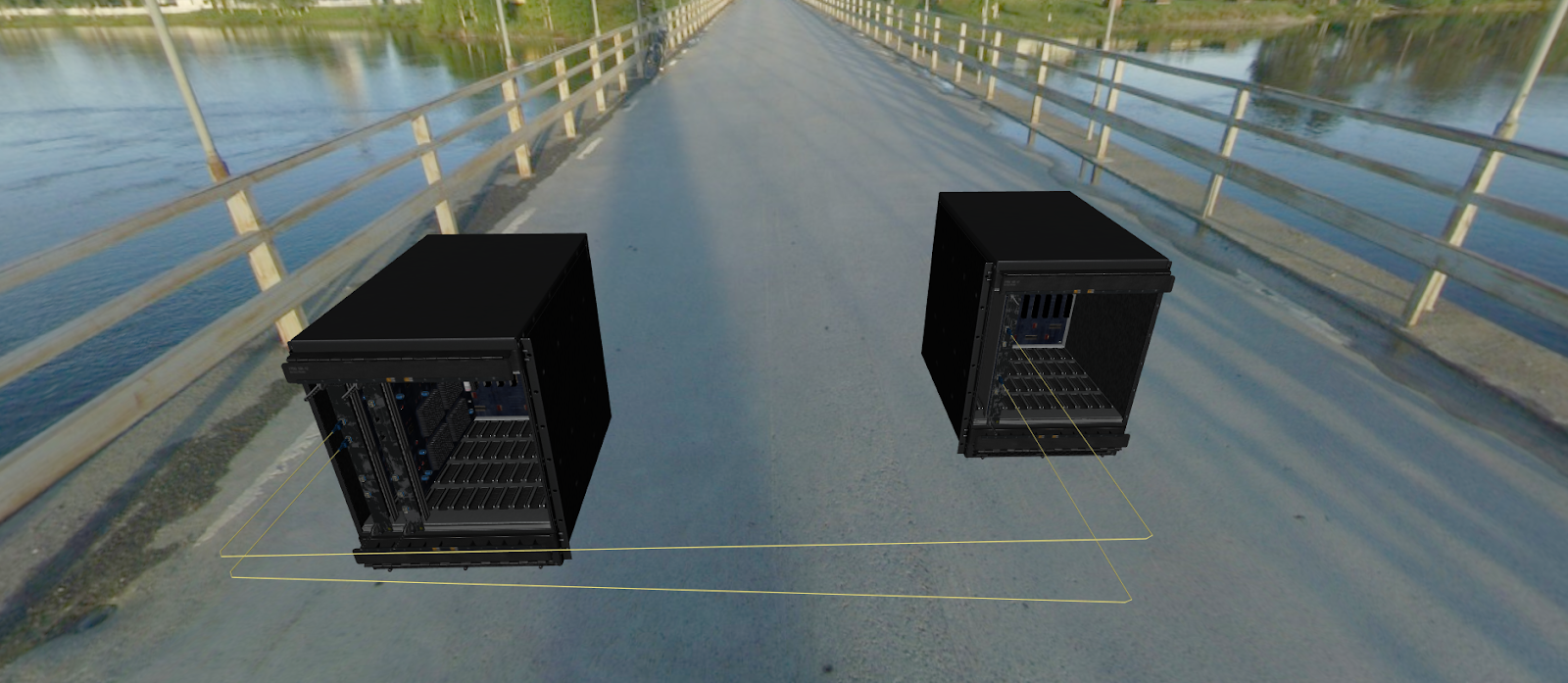
Fig.1 Two chassis example
2. The auto layout problem
In practice, we will have at least 8 chassis, each chassis will have up to 12 cards, each card has 0 - 48 ports, we want to connect any of two ports in different cards. Note the auto layout algorithm should be generic, not just support 8 chassis with 12 cards.
For example, we added a third chassis, and use fiber to connect the first chassis to the third chassis. It looks like this

Fig.2 Three chassis example
Which looks fine.
But if I move the card of the third chassis to right, then the fiber cable breaks through the first chassis to connect to the third chassis, which is not expected. See the image below.
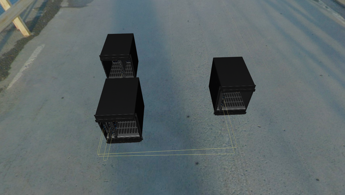
Fig.3 Three chassis example (unexpected fiber cable breakthrough)
Let’s adjust the camera to show the cable breakthrough more clearly.
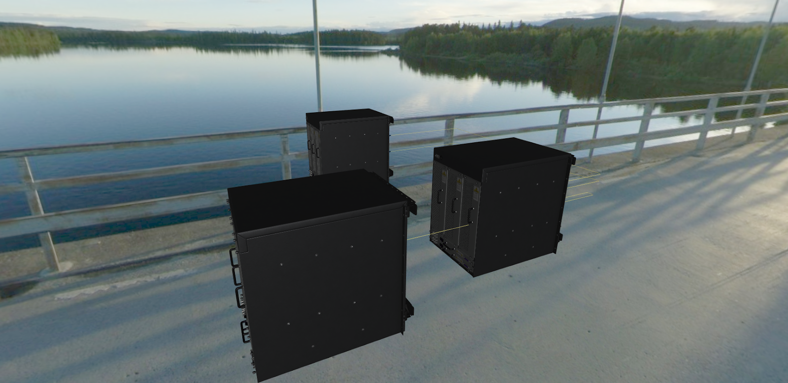
Fig.4 Three chassis example (unexpected fiber cable breakthrough) close-up of Fig.3
We need to auto layout the cable according to the positions of chassis and cards to avoid such a breakthrough. That’s the problem we need to resolve in this challenge.
3. JSON driven rendering
The existing app uses a JSON file to describe the positions of chassis, cards and their connection. The JSON file located in the viewer/data/data.json.
Here are two JSON samples of Fig.2 and Fig.3. for your reference.
( Note the actual JSON file contains extra fields, but these fields are irrelevant to the model description so I omitted here)
(1) Fig.2 JSON
{
"models": [
{
"type": "Chassis",
"children": [
null,
{
"type": "IMMCard",
"numPorts": 4
},
null,
{
"type": "IMMCard",
"numPorts": 6,
"emptyPorts": [30, 33]
}
],
"position": [-80, 0, 40]
},
{
"type": "Chassis",
"children": [
null,
{
"type": "IMMCard",
"numPorts": 4
}
],
"position": [80, 0, 0]
},
{
"type": "Chassis",
"children": [
null,
{
"type": "IMMCard",
"numPorts": 6
}
],
"position": [-100, 0, -80]
},
],
"connections": [
[[0, 1, 30], [1, 1, 30]],
[[0, 1, 33], [1, 1, 40]],
[[0, 3, 40], [2, 1, 40]]
]
}
Here is a description of the JSON
-
models: an array, describes the models existed in the app. Here it describes there are 3 chassis. Each chassis is an object, which contains the following fields
-
type: fixed to "Chassis"
-
children: an array, describes the cards that the chassis contains. The array has up to 12 elements, each element represents a card slot of the chassis. If the element is null, then it means the slot is empty. If the slot is inserted a card, then an object represents the card presents, the card object contains the following fields:
-
type: fixed to "IMMCard"
-
numPorts: can only be following numbers
-
0: The card has no ports.
-
4: The card has 4 ports, the available port index are [30, 33, 40, 43].
-
6: The card has 6 ports, the available port index are [27, 30, 33, 40, 43, 46]
-
10: The card has 10 ports, the available port index are [37-46]
-
12: The card has 12 ports, the available port index are [13-24]
-
30: The card has 30 ports, the available port index are [1-10, 25-34, 37-46]
-
40: The card has 40 ports, the available port index are [1-20, 25-44]
-
48: The card has 48 ports, the available port index are [1-48]
-
-
emptyPorts: an optional field. It’s an array, contains the port index, indicates which ports are not inserted by SFP ports. Empty ports can’t be connected.
-
-
position: The 3D position of the chassis.
-
-
connections: an array, describes the connections between different chassis. Each element represents a connection. Here there are 3 connections. Each element is also an array, here is the format description of the connections element.
-
the format is [FROM, TO], where FROM and TO are both arrays with 3 elements. It means the fiber connects from FROM to TO.
-
Each FROM or TO has 3 elements, the format is [Chassis index, Card index, Port index]. Note the chassis index is the 0-based index of the element in the models array. The card index is the 0-based index of the element in the children array of that chassis. The port index must be in the available port index according to the value of numPorts.
-
For example [[0, 1, 30], [1, 1, 30]] means, the fiber connection starts from “chassis 0 ‘s card 1’s port 30” to “chassis 1’s card 1’s port 30”.
-
(2) Fig.3 JSON
{
"models": [
{
"type": "Chassis",
"children": [
null,
{
"type": "IMMCard",
"numPorts": 4
},
null,
{
"type": "IMMCard",
"numPorts": 6,
"emptyPorts": [30, 33]
}
],
"position": [-80, 0, 40]
},
{
"type": "Chassis",
"children": [
null,
{
"type": "IMMCard",
"numPorts": 4
}
],
"position": [80, 0, 0]
},
{
"type": "Chassis",
"children": [
null,
null,
null,
null,
null,
null,
null,
{
"type": "IMMCard",
"numPorts": 6
}
],
"position": [-100, 0, -80]
},
],
"connections": [
[[0, 1, 30], [1, 1, 30]],
[[0, 1, 33], [1, 1, 40]],
[[0, 3, 40], [2, 7, 40]]
]
}
You see the difference between the JSON of Fig.3 and Fig.2 is the third chassis (chassis 2), its card is moved from index 1 to index 7. So the third connection is changed from [[0, 3, 40], [2, 1, 40]] to [[0, 3, 40], [2, 7, 40]].
We are able to add/remove/change chassis, cards, and connection freely by changing the JSON data, as long as we adhere to the JSON format.
4. Fiber cable modeling code
Fiber cables are modeling purely by code. We used THREE.TubeBufferGeometry
and THREE.MeshStandardMaterial to model and render the cable.
The key function is getPoint function of CurveLine class. You can read the viewer/src/modelObjects/cable.js for more details.
getPoint(t) {
let tx, ty, tz;
if (t < 0.1) {
tx = this.startPoint.x;
const heightYRange = (this.height) - this.startPoint.z;
const delta = (t - 0) / (0.1 - 0);
ty = this.startPoint.y;
tz = this.startPoint.z + delta * heightYRange;
} else if (t > 0.9) {
tx = this.endPoint.x;
const heightYRange = this.endPoint.z - this.height;
const delta = (t - 0.9) / (1 - 0.9);
ty = this.endPoint.y;
tz = this.height + delta * heightYRange;
} else {
const delta = (t - 0.1) / (0.9 - 0.1)
tx = this.startPoint.x + delta * this.xRange;
ty = this.startPoint.y + delta * this.yRange;
tz = this.height
}
return new THREE.Vector3(tx, ty, tz).multiplyScalar(this.scale);
}
The getPoint defines the equation of the cable, it tells THREE.TubeBufferGeometry
the shape of the cable. The code above defines the cable is a polyline, the render results are shown as Fig.1-Fig.4.
You are expected to modify this getPoint function, to make sure the cable can auto layout properly.
5. Restrictions & Goals of the auto layout algorithm
The auto layout algorithm must fit all the following restrictions.
-
Every chassis should face to the same orentation.
-
No two chassis stay side by side, that means one chassis should be slightly ahead of the other.
-
The cable should not be overlapped with other cables.
-
If two cables are across, one cable should have a small jump.
-
The cable cannot break through any chassis or cards.
-
We are allowed to adjust the position of chassis slightly to make the auto layout algorithm workable, but relative positions of models should keep same.
-
The JSON driven rendering should be supported, hard coding models properties in the code is not allowed.
6. Dot algorithm migration
We have investigated a 2D algorithm, called Dot algorithm. Graphviz adopted it to draw diagrams. The basic idea of Dot algorithm is to rank each node of the graph, and use spline to draw the connections. We want to migrate Dot algorithm to our three.js app. But there is a slight difference - the connections on the three.js app is 3D, but the Dot algorithm is 2D. However, we can assume all chassis are placed in the same 2D plane, so the 3D position (y coordinate) is only affected by the positions of ports of cards. I assume this is only a slight effect of the Dot algorithm.
Notes
This goal of this challenge is more focused on a workable solution, we need to make the auto layout workable and aesthetic. All the scoring will be based on the restrictions & goals listed in Section 5. Minor issues like coding style, best practice will only be counted if there is a tie. That means, we prefer to accept the workable algorithm implementation with some coding style issues, rather than getting a non-workable implementation with perfect coding styles.
Review
The review will be performed by the copilot (and the PM) subjectively. So there is no appeal and appeal response phase.
Checkpoint phase
We added a checkpoint phase in this challenge, all submissions that submitted before Jan 9, 2019 8:00 AM EST will be considered as checkpoint submissions. We will provide preliminary feedback to all checkpoint submissions, you can submit again after the checkpoint phase. We will choose 5 checkpoint winners, each winner will receive $100 (not included in the main prize $2000/$1000). So the final winner will receive $2100 potentially.
Important deadline
- Checkpoint submission phase deadline: Jan 9, 2019 8:00 AM EST
- Final submission phase deadline: Jan 14, 2019 8:00 AM EST
Final Submission Guidelines
Please submit all the following items in a zip archive.
- The updated source code of the app
- A writeup to describe the auto layout algorithm detailedly.
- A video to demonstrate the algorithm is workable.